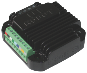
 UIM241XX controllers are miniature stepping motor controllerswith RS232 communication protocol. They can be mounted ontoNEMA 17/23/34/43 series stepping motor seamlessly through corresponding flanges. The user controls the UIM241XX motion controller via RS232 commands. The instruction structure is simple, high fault tolerance. It can be operated by users who know nothing about the stepping motor drive. UIM241XX controllers support open-loop and quadrature encoder (QE) closed-loop control. With UIM241XX advanced motion control, selected NEMA 23 motors can ramp up to 4000 RPM in 0.25 seconds (Based on 1.8° motor) .The enclosure is made of die-cast aluminum which provides a rugged, durable protection and improves the heat dissipation.
To purchase a sample, please visit ServoElements.com
Description
| Stepping Motor Port | ||
|---|---|---|
| Port | Description | |
| A+ /A- | Stepping motor's A phase wiring | |
| B+/ B- | Stepping motor's B phase wiring | |
| Connection Port | ||
| Port | Symbol | Description |
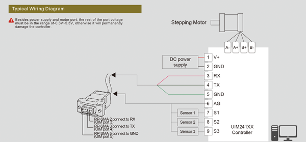
| 1 | V+ | Positive Voltage: 12-48 VDC (Note: Max voltage is different between 242Lxx, 242Cxx and 242Hxx) |
| 2 | GND | Ground voltage: 0V (Positive and negative can not be wrong) |
| 3 | RX | To the RX pin on user device |
| 4 | TX | To the TX pin on user device |
| 5 | GND | To signal ground on user device |
| 6 | AG | Analog Input |
| 7 | S1 | Sensor Signal Input 1 |
| 8 | S2 | Sensor Signal Input 2 |
| 9 | S3 | Sensor Signal Input 3 |
Character
Micro-intergrated Design
• Miniature size 42.3mm x 42.3mm x 42.3mm
• Integral design design to fit most motors, work independently as well
• Made of die-cast aluminum which provide a rugged, durable protection and improves the heat dissipation
Embedded DSP Microprocessor
• Hardware DSP, 64 bit calculation precision
• Linear/ non-linear acceleration/ deceleration
• S-curve, PT/ PVT position control
• Support quadrature encoder, closed loop control
• 3 sensor input ports, includes 2 12-bit analog input ports
• 10 programmable real-time event base change notifications
• 13 programmable actions triggered by 8 sensor events
Motor Drive Characteristics
• 14-48VDC input voltage
• 1 to 16th micro stepping, dual full H-bridge with PWM constant current control, online controlled offline/enable
• Accurate subdivision and current control, selected NEMA 17/23 motors can ramp up to 4000 RPM
Communication Characteristics
• RS232 3-wire serial communication
• Max baud rate 57600bps
Diagram
Downloads
Catalog Page: UIM241.pdf
StepEva Software: StepEva3.4.3.zip

