 UIM240C04P
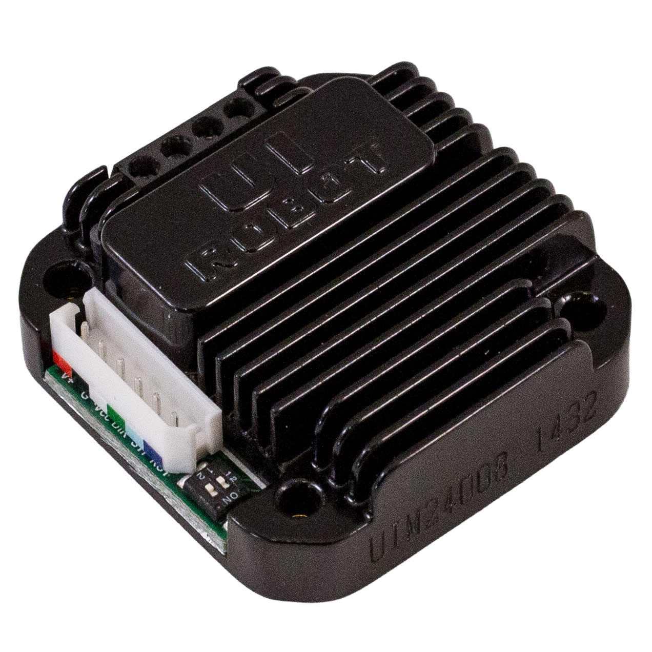
Micro-high-performance stepping motor driver featuring small size that can be mounted onto NEMA 17/23/34/43 series stepping motors seamlessly through corresponding flanges.
- 12 – 38VDC Input Voltage
- Peak 4A Adjustable Output Current
- Dual full H-bridge with PWM constant Current control
- Online controlled offline/enable
- Highest frequency 12KHz/1 stepping 200KHz/1/16 micro-stepping
High-speed Current compensates for the impact caused by back-EMF when the motor is running at high speed.
Drive enclosure is made of die-cast aluminum which provides rugged, durable protection and improves the heat dissipation.
$159.00 USD /ea
1 item in Stock
Call (360) 601-0666 or email orders@machmo.com to place an order!
Description
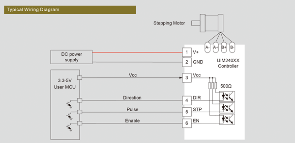
| Stepping Motor Port | ||
|---|---|---|
| Port | Description | |
| A+ /A- | Stepping motor's A phase wiring | |
| B+/ B- | Stepping motor's B phase wiring | |
| Connection Port | ||
| Port | Symbol | Description |
| 1 | V+ | Positive Voltage: 12-48 VDC (Note: Max voltage is different between 242Lxx, 242Cxx and 242Hxx) |
| 2 | GND | Ground voltage: 0V (Positive and negative can not be wrong) |
| 3 | VCC | Common anode input, positive electrode of pulse, direction, and off-line signals is connected to the terminal |
| 4 | DIR | Direction signal input, High/ Low-level key for rotation direction control and vacancy for the high level |
| 5 | STP | Step pulse input, the falling edge is a valid pulse |
| 6 | ENA | Off-line signal input. Low level means the rotor in a free state, high or vacant means the motor be controlled |
Character
Micro-integrated Design
• Miniature size 42.3mm x 42.3mm x 16.5mm
• Integral design to fit most motors, driver can also work independently
Diagram
Download
User Manual: UIM240 Series.pdf