Critical Speed Limits Chart for Lead Screws and Rolled Ball Screws
Use screw speed, unsupported length and bearing support to read the critical-speed chart for lead screws and rolled ball screws.
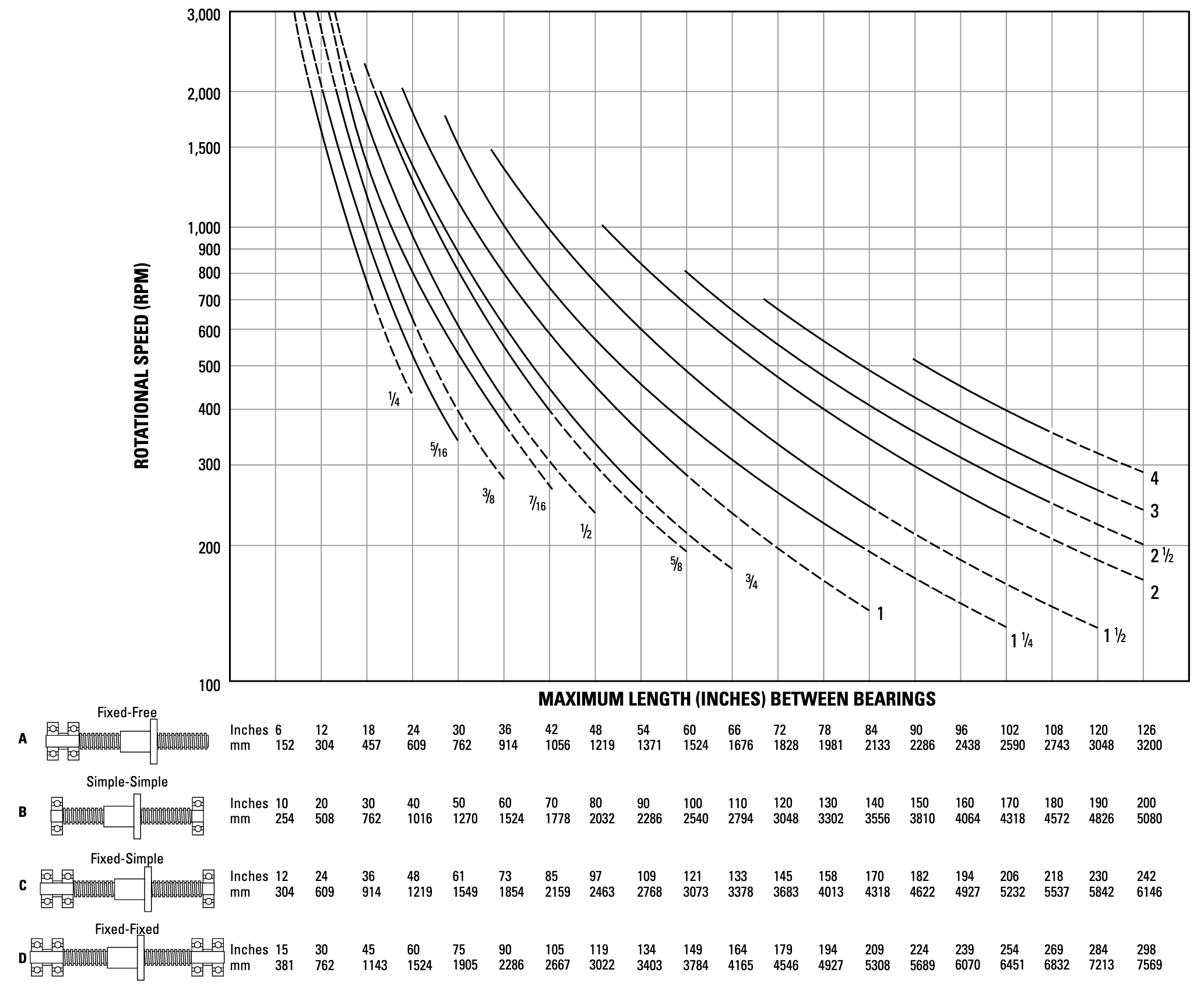
Every screw shaft has a rotational speed limit at which rotation produces excessive vibration. The type of end bearing support changes this critical speed.
How to use the chart
- Determine the required rotational speed in RPM and the maximum unsupported length between bearing supports.
- Select the matching end support: A, fixed–free; B, simple–simple; C, fixed–simple; or D, fixed–fixed. Use that support’s length scale beneath the chart.
- Locate the intersection of the required RPM (horizontal grid lines) and unsupported length (vertical grid lines), then compare it with the screw-diameter curves.
The original guidance recommends operating at no more than 80% of the critical speed to allow for misalignment and lack of screw straightness. If the operating point falls within a dashed portion of a curve, consult the manufacturer.
Maximum RPM limit: The curves use the smallest root (minor) diameter of standard screws within each nominal size range. They stop at the maximum ball nut rotational speed. Do not exceed that RPM, regardless of screw length.
Critical-speed limits chart
Open the full-size chart (PNG, 2066 × 1694; opens in a new tab)
Source and related resources
This article was originally published on October 27, 2018, with content and a chart attributed to Thomson BSA. The original chart is reproduced unchanged. See Thomson’s screw critical-speed guidance for the manufacturer’s current reference.